
Instructions for the Use of KY1-B2 Single-Phase Closed-Loop Trigger
I. Overview
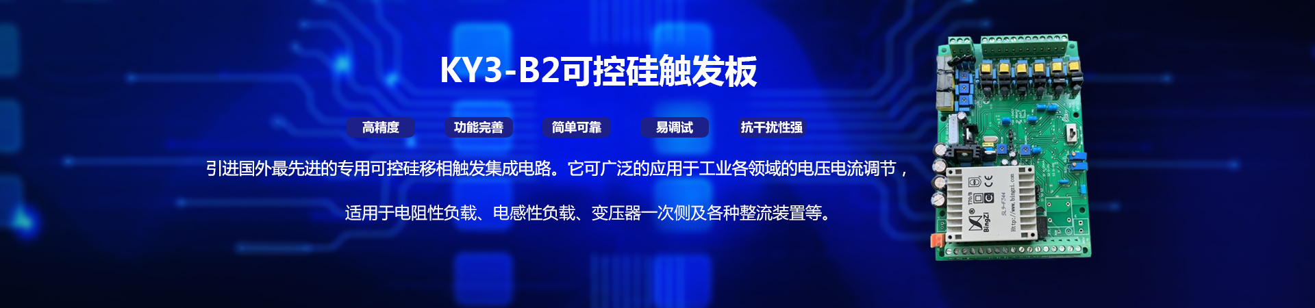
KY1-B2 single-phase closed-loop flip-flop is a special silicon controlled phase shift trigger integrated circuit imported from abroad. The output trigger pulse has high symmetry and stability, and does not change with ambient temperature. It contains complete fault protection functions such as constant current, constant voltage, over current and over heat. It has the advantages of high accuracy, perfect function, simple and reliable use, easy debugging and strong anti-interference. It can be widely used in voltage and current regulation in various fields of industry. It is suitable for resistive load, inductance load, primary side of transformer and various rectifier devices. It is mainly used in high-power power supply, AC and DC voltage regulation, salt bath furnace, power frequency induction furnace, quenching furnace, temperature heating control of molten glass and various industrial furnaces; rectifier transformer, power dispatcher, primary side of electric furnace transformer, magnetizing and demagnetizing regulation, DC motor speed regulation, single-phase motor soft-start energy-saving device; with nickel, ferrochromium, far infrared heating elements and silicon-molybdenum rod, silicon. Temperature control of heating elements such as carbon rods, etc.
Ⅱ. Performance characteristics
○The requirement of phase-disorder is limited. It can be used in power supply of 220 V and 380 V power supply frequency of 50/60 Hz power grid.
○It can directly interface with the output signals of various control instruments (temperature controllers) and microcomputers at home and abroad.
○It is suitable for resistive load, inductive load, primary side of transformer and other load types.
○It has soft start and soft stop function, reduces the impact interference to the power grid, and makes the main circuit more safe and reliable.
○Driving power is strong, each circuit can output 500 mA of current, can drive 4000A thyristor.
○Fault alarm output function. (External buzzer and indicator)
○Urgent stop function.
○Current limiting and over-current protection function.
○Temperature control and protection function end.
○Open-loop and closed-loop (constant current and voltage) control modes.
○Integration structure: power supply, synchronous transformer, trigger control circuit and pulse transformer are integrated. Structural tightness, easy debugging, simple wiring.
Ⅲ.Main Technical Indicators and Their Use
Input signal: 4-20mA (short connection S1 is selected by JP2 jumper) DC 0-5V (short connection S2 is selected by JP2 jumper) DC 0-10V (short connection S3 is selected by JP2 jumper) 10K potentiometer (manual adjustment)
Output Specification: Single-phase or two-phase two-way trigger 0-100% output.
Phase shift range: 0-170.
Trigger capacity: <4000A thyristor.
Current Limiting: 110% rated current, balance time 0.5S.
Over-current protection: The threshold of over-current is adjustable, the output pulse is blocked, and the operation time is 10 mS until shutdown. After the breakdown is removed, the power supply must be restarted before it can work normally.
Indicating function: DS2_PWL working power supply indication
DS1_OFF Fault Indication
Power usage: AC1 and AC2 are connected to 220V or 380V main power supply. When inputting 380V main power supply, be sure to select input through JP1 jumper, otherwise transformer will be damaged (220V input is selected when leaving the factory).
Load test: SCR can not work properly without load or current less than 0.5A when testing trigger. So the load current should be greater than 0.5A.
IV. Working methods
1. Open-loop or closed-loop operation modes.
○The trigger chooses open-loop or closed-loop (constant current and constant voltage) mode by switching K1 switch. (Refer to wiring figure 1).
○The flip-flop can access AC feedback signals of current 0-100mA and voltage 0-3V for AC constant current and voltage control.
○Flip-flops can be sampled according to different requirements. The trigger can also form an external closed-loop automatic control system with a single-chip computer and corresponding detection sensors.
2. Three input control modes can be selected:
○4-20mA input. Short connection S1 is selected by jumper.
○0-5V input. Choose short connection S2 through jumper.
○0-10V input. Select short connection S3 through jumper.
3. Current limiting function:
The flip-flop can limit the output current by adjusting the VR2 (XL) variable resistance. Adjustment can be made according to the actual load current.
Clockwise amplification.
4. Protection function:
The trigger is connected to the current feedback signal. The over-current protection function is controlled by adjusting VR1 (GL) variable resistance.
Note: Variable resistors on circuit boards are not allowed to be changed by other potentiometer users except VR1 and VR2 users.
5. Connection protection switch: External temperature control protection switch can be connected (refer to the control wiring diagram).
V. Conversion Switch K1 Function
1. Conversion constant current, transverse voltage or open-loop operation can be selected according to user's usage.
2. Flip-flops can only be used for general voltage regulation in open-loop operation.
Ⅵ. Feedback Mode
1. Refer to trigger board wiring diagram for feedback wiring method.
2. When the current feedback of VF and IF power supply is connected at the same time, it can be converted into voltage stabilization and current stabilization by K1 switch, and has the function of current limiting and over-current protection.
3. No voltage and current feedback can only be used for general voltage regulation.
4. Single-access voltage feedback can be used as a regulator.
VII. Exclusion of Abnormal State
1. When the input control signal is small, the SCR is close to 100% or does not work properly.
○It is possible that the phase of the power supply of the trigger is not correct. Please adjust the phase of the power supply on the trigger board.
○If the function conversion switch operates in stable voltage or current state, and the voltage or current feedback signal is not connected or contacted poorly. Please check whether the feedback signal is connected correctly.
○Double closing is the best choice for thyristor control line to prevent interference.
2. SCR has no output, no current or voltage:
○The panel DS2 indicator is not on and the SCR cannot work. Please check whether the power supply of the trigger is connected correctly.
○Check whether the DS1 (OFF) indicator light is on. If the light is on, please turn off the power supply and restart it.
3. Trigger users can not solve the problem, please do not hesitate to contact our company, we will solve it for you in time.